Tutorials in this section:
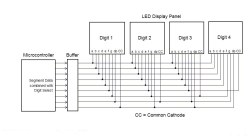
Multiplexing LED displays can make them more efficient by using fewer components, simplifying the printed circuit board, and consuming less power. One segment from each of the digits is connected to a common line which is controlled by a single output pin from the microcontroller. This is done for each segment on a digit, so only seven output drive pins are needed for a multi-digit seven-segment display panel to control all the segments. Likewise, fourteen output pins are needed for a fourteen segment display panel, and so on.
Of course, only one digit is activated at a time using this method, as each digit is enabled one at a time in sequence by a separate signal which connects to the common cathode (or common anode) pin on a digit. There would be a separate control line from the microcontroller output port for each digit on the display panel. The segment data lines are updated for each digit as it is selected by its separate digit select control line. This makes sure that each digit on the panel displays the intended information, which could be a number, letter, or some other symbol.
The brightness of a panel is lower on a multiplexed panel because of this on-off duty cycle, but the light intensity can be increased to an acceptable level by a small increase in LED current. Also, the LED update frequency can be made high enough so that there wouldn't be any noticeable flickering.
Using separate control signals for each digit in this fashion can be inefficient in a way because only one control line signal is activated at a time while the others are left in an idle state. Each of the segment data lines are being continually used, while the digit select control lines are each used only part of the time. For example, each control line is active only 25% of the time in a four digit display.
A more efficient method of multiplexing would be to combine the segment data lines and the digit select control lines into the same set of lines such that each line can alternate between driving individual segments and selecting a digit. The example diagram below shows how the lines are connected in this way as a four digit seven-segment common-cathode display with a decimal point. Only nine pins from the microcontroller can control the entire display. A digit would need a total of eight drive pins to control the segments plus one extra one to provide the common anode or cathode connection.
Click to enlarge
Five of the segment data lines operate the same as before, while the lower four segment lines are combined with the digit select lines. As a digit is selected, the segment data lines supply the source current for the individual segments while the digit select line is activated which sinks the current. The same segment data is also applied to each of the other digits, but they are not activated because there would be no way to sink the current.
For this to work, each four lower lines need to operate in a tri-state mode, where the third state is a high-impedance state that can neither source nor sink current. A non-selected segment on a selected digit would have to be in this third state because if it went low, it could inadvertently select another digit at the same time. The only time a control line goes low would be to select a digit. The only time a control line goes high would be to energize a segment on the selected digit. There is also one other problem in that a segment on one digit might be connected to a different segment on another. For example, segment ‘g’ on digits one and two is connected to segment ‘f’ on digit 4.

