Tutorials in this section:
The differential gain of a basic operational amplifier by itself with no feedback connected can be very high, in the order of 120 dB (1,000,000) or more. Even the slightest change of a few microvolts across the two input terminals (inverting and non-inverting inputs) can cause the output to swing back and forth between the voltage supply rails. The amplifier is extremely unstable if any attempt is made to drive the output voltage at some point between its maximum and minimum levels. About the only type of application that this op amp circuit would be useful for is a voltage comparator circuit.

In order to benefit from an op amp's special characteristics, and to provide control over the output signal, some sort of feedback must be used.
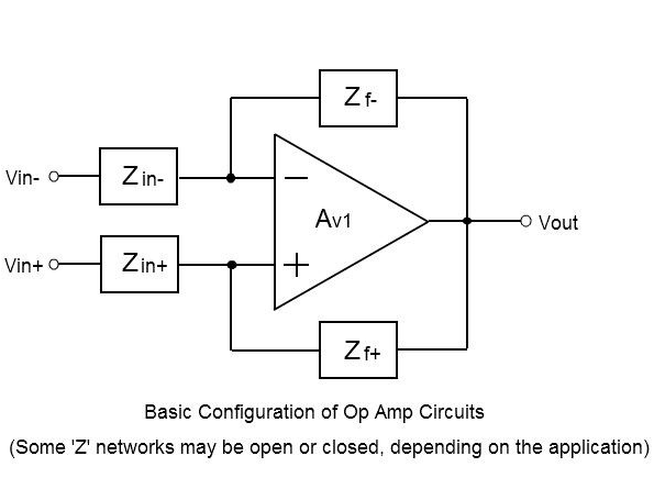
A feedback component (or components) must be connected from the output to either the inverting input or the non-inverting input or both inputs, which will then enable precise control over the circuit’s operating characteristics.
The values of the components and how they are connected will determine circuit behavior, and usually the electrical parameters of the op amp itself can be factored out of most calculations. Because of the op amp's extremely high input resistance, low output resistance, and high voltage gain, it is possible to do the basic calculations while assuming ideal op amp characteristics.
If this feedback component is connected from the output to the non-inverting input, this would be considered Positive Feedback, and the op amp still wouldn't be of any use as an amplifier, but it could be made to oscillate in a controlled fashion determined by component values, or it could be a comparator with hysteresis.
The circuit could operate independently of any input applied to it, and can be used in applications like signal generators, which can generate a sine wave, repetitive pulses, sawtooth waveforms, etc.
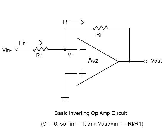
The most common type of op amp circuit uses Negative Feedback, where the feedback component is connected from the output to the inverting input. The output is driven to a level that would keep the two inputs at essentially the same voltage potential. This provides precise control over the gain of the amplifier, as the gain determined by the feedback network is many orders of magnitude lower than the gain of the op amp itself.

In this case the op amp would generate an amplified signal on the output as a function of some input applied to it, and could be used in applications like differential amplifiers, voltage and current regulators, filters, converters, analyzers, etc. Many mathematical functions can also be performed, such as adding, subtracting, multiplying, dividing, integrating, differentiating, plus an assortment of trigonometric functions and other specialized functions.
Sometimes, op amps circuits are designed with a combination of positive and negative feedback, and this would be useful in applications like current sources, current amplifiers, current to voltage converters, etc.
In many circuits, the designer would need to consider that feedback applied to the negative input can become positive if the feedback network has any phase-shifting components.
Likewise, feedback applied to the positive output can become negative under similar conditions. In order to reduce instability, the designer needs to be careful about any stray capacitances introduced into the network.
It would also be a good idea to follow the recommended compensation techniques on the op amp data sheet. The finite bandwidth of the op amp may also introduce phase shift and instability at higher frequencies, so the designer would need to analyze the gain-bandwidth diagrams in cases like these.
